If you’ve ever stood in front of a machining center at a job shop, watched the tool cut through a block of aluminum like it was butter, or stared at a finished part with tight tolerances, you’ve probably wondered: how do these machines know how fast to move that cutting tool? The answer boils down to one of the most fundamental, yet often misunderstood, parameters in CNC machining: feed rate. As a machining center supplier who’s worked with job shops, prototype labs, and high-volume production facilities for over a decade, I’ve seen too many operators and even new CNC programmers misinterpret feed rate—and that mistake can cost you hours of downtime, ruined parts, or even damage to your machine. Let’s break this down clearly, no jargon overload, just practical, science-backed info that matters for anyone who uses or buys machining centers. Machining Centers
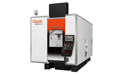
First, let’s get the basic definition right. Feed rate is, simply put, the speed at which the cutting tool moves relative to the workpiece during a machining operation. But it’s not a one-size-fits-all number, and it’s not the same as spindle speed, which is how fast the tool spins. Think of it this way: spindle speed is like how fast you spin a knife, and feed rate is how fast you push that knife into the bread to slice it. Push too fast, and you’ll tear the bread; push too slow, and you’ll spend way too much time slicing. The same logic applies to metal, plastic, or composite parts cut on a machining center.
Now, how is feed rate measured? That’s where it gets specific, because there are three common units used in CNC programming, and mixing them up is a top cause of errors in our shop. For mills (the most common type of machining center), the standard units are inches per minute (IPM) or millimeters per minute (mm/min). That’s the linear speed of the tool along the X, Y, or Z axis relative to the workpiece. But there’s another, equally important unit: inches per tooth (IPT) or millimeters per tooth (mmT), which refers to how far each tooth on a multi-tooth cutting tool advances into the material during one spindle revolution. Then there’s feed per revolution (IPR or mmR), which is the total distance the tool advances per full spin of the spindle.
Let’s use a real example to make this concrete. Suppose you have a 4-flute end mill, running at a spindle speed (RPM) of 1,000. A common IPT for aluminum is 0.008 inches. To calculate IPM, you multiply RPM by number of flutes by IPT: 1,000 * 4 * 0.008 = 32 IPM. That means the tool will move 32 inches every minute. If you mixed up IPT with IPM, you’d end up with a feed rate 500 times too high, which would snap the end mill instantly or leave a lousy surface finish. That’s the kind of mistake that costs a shop a $50 end mill, a $200 block of 6061 aluminum, and half a day of downtime. I’ve seen it happen twice last year alone, so don’t underestimate the importance of unit clarity.
Next, what factors actually determine the right feed rate for your job? It’s not a guess; it’s a balance of four key variables, all of which a good machining center supplier will walk you through when you’re purchasing or programming a new machine.
First, the material you’re cutting. Soft materials like wood, aluminum, or low-carbon steel let you run a much higher feed rate than hard materials like titanium, hardened tool steel, or Inconel. For example, a 2-flute carbide end mill cutting pine might run at 200 IPM, but that same end mill cutting titanium would top out at 10 IPM—hardly the same. The material’s hardness, thermal conductivity, and how it chips or flushes away from the cut (called chip evacuation) all play into this. If you’re machining a material that doesn’t form small, tight chips (like soft aluminum), you have to slow down feed rate to prevent chips from clogging the flutes of the tool, which would cause overheating and breakage.
Second, the tool type and condition. The number of flutes on an end mill matters a lot—more flutes mean you can feed faster, right? Not exactly. More flutes mean more cutting edges removing material per revolution, which can boost productivity, but they also leave less space for chips, so you have to adjust feed rate to avoid chip packing. A 2-flute end mill is better for deep cuts or materials that produce big chips, so you can run a bit faster with fewer flutes. Tool material is another factor: solid carbide tools can handle much higher feed rates than high-speed steel (HSS) tools, which soften at lower temperatures. Even the tool’s sharpness matters: a dull tool will require a 20-30% lower feed rate than a sharp one, because it’s rubbing instead of cutting, generating more heat that damages the part and the machine.
Third, the machining operation itself. Feed rate is different for roughing, finishing, and specialized operations. Roughing is all about removing as much material as fast as possible, so you run a high feed rate and a slightly less precise finish, since you’ll follow up with a finishing pass anyway. Finishing is the opposite: you run a lower feed rate to get a smooth surface and tight dimensional tolerance—for example, a finishing pass on a mold cavity might use a feed rate half that of the roughing pass to avoid chatter marks or surface roughness. Special operations like tapping, thread milling, or contouring also have unique feed rate rules: when tapping, feed rate has to exactly match spindle speed to get the right thread pitch, so if your spindle is spinning at 500 RPM, your tap feed rate is 500 mm/min to make a 1mm pitch thread. Get that wrong, and you’ll snap the tap inside the workpiece—a nightmare to extract.
Fourth, your machining center’s capabilities. This is where a supplier’s input is invaluable. Not all machining centers are built the same: high-torque, rigid industrial machining centers built for heavy material removal can handle much higher feed rates than smaller, lower-torque benchtop models. The machine’s axis accuracy, acceleration/deceleration (look-ahead capability), and spindle power all set hard limits on what feed rate you can safely run. For example, a machine with a 10,000 RPM spindle and high-speed linear motors can run a 4-axis contouring operation at 500 IPM, while a basic 3-axis benchtop might max out at 100 IPM for the same tool and material. Running a feed rate above your machine’s capability will cause axis drift, part errors, or even damage to the machine’s drives.
Now, why does feed rate matter beyond just making a good part? Let’s talk about business impacts, because that’s what our customers care about most. The right feed rate cuts cycle time: if you run a 10% faster feed rate, you finish a job 10% sooner, which means more jobs per month, lower labor costs per part, and faster ROI on your machining center investment. But get it wrong, and you pay dearly. Too slow, and you’re wasting machine hours that could be used for other jobs. Too fast, and you get tool breakage, scrapped parts, and potential machine damage. I had a customer last quarter who tried to run a roughing pass on titanium at twice the recommended feed rate; he broke a $300 end mill, ruined a $400 block of material, and had to wait 3 days for a replacement part for his machining center’s Z-axis drive—costing him over $2,000 in lost production. That’s not an anomaly; it’s why we prioritize teaching our customers how to set feed rates correctly when we install their machines.
Common misconceptions about feed rate abound, so let’s clear up a few more. First, feed rate is not the same as cutting speed, which is a term for the surface speed of the tool relative to the workpiece (in feet per minute, or surface feet per minute, SFM). Cutting speed and spindle speed are directly related, but feed rate is a separate variable, and changing one doesn’t automatically change the other. Second, higher feed rate isn’t always better for productivity. If you run a feed rate that’s too fast for your tool, you’ll have to stop and replace the tool every few minutes, which adds more downtime than you saved by feeding faster. It’s a balance: the optimal feed rate is the one that gives the lowest cost per part, not the highest possible speed. Third, feed rate can be adjusted dynamically by modern machining centers. Many new CNC mills have adaptive control software that monitors tool load in real time and adjusts feed rate automatically as it cuts through variations in material hardness or changes in cut depth. That’s a huge upgrade from older machines that run a fixed feed rate no matter what, and it’s why we build that adaptive capability into most of our mid-range and industrial machining centers.
Now, how do you set the right feed rate for your specific job? For new operators, we always recommend starting with the tool manufacturer’s guidelines. Every end mill, drill, or tap comes with a feed rate table based on tool material, number of flutes, and workpiece material. That’s a great baseline, but you should adjust it based on your machine’s rigidity, your desired finish, and your experience. For example, if you’re running a machining center on a shop floor with a lot of vibration, you might want to cut your feed rate by 10-15% to avoid chatter. For high-volume production runs, you can test a small part first: run a 1-inch test cut at your desired feed rate, check the tool wear, surface finish, and dimensional accuracy, then tweak the feed rate up or down until you get the best result.
As a machining center supplier, our job isn’t just to sell machines—it’s to make sure our customers get the most out of them. That means walking through feed rate basics at machine setup, providing custom feed rate tables for common materials and operations, and troubleshooting when a job isn’t running as expected. We’ve even developed a free online feed rate calculator for our customers that lets you input your tool type, material, and machine specs to get a recommended baseline, which we update regularly with new tool and material data.

If you’re in the market for a new machining center, or you’re looking to upgrade your current setup to run higher feed rates and reduce cycle time, let’s connect. Whether you’re a small job shop with 3 machines or a large production facility with 20+, we can help you find a machining center that matches your feed rate needs, train your team on proper feed rate programming, and support you as you scale your production. Don’t let incorrect feed rates hold your shop back from higher productivity and lower costs. Let’s start a conversation today.
Vertical Machining Centers References
- Smid, P. (2019). CNC Programming Handbook (3rd ed.). Industrial Press Inc.
- DeVries, W. R. (2018). Analysis of Metal Cutting Operations. ASME Press.
- National Institute of Standards and Technology (NIST). (2021). “Feed Rate Optimization for CNC Machining of Hard Materials.” NIST Technical Note 1972.
- Tooling & Manufacturing Association (TMA). (2020). “Recommended Cutting Speeds and Feed Rates for Common Engineering Materials.” TMA Technical Bulletin 412.
Hermens Industrial Co., Ltd.
As one of the most professional machining centers enterprises in China, we’re featured by quality products and low price. Please rest assured to buy cheap machining centers in stock here and get quotation from our factory. We also accept customized orders.
Address: 9/59 Moo 14, Rachathewa , Bang Phli , Samut Prakan Province 10540
E-mail: liu_jincheng@hzhemen.com
WebSite: https://www.hermensindustrial.com/
